
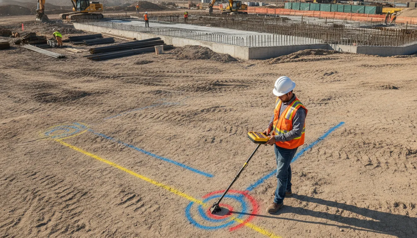
A utility map is useful when the project team understands what it documents, how it was produced, and how the information can be carried into design and construction workflows. That is why the scope of the map and the format of the handoff should be agreed before fieldwork begins.
Contact SafeLine about your mapping scope.
Typical underground utility mapping deliverables may include a detailed site map, field markings with depth approximations, verification photographs, written documentation, and CAD-compatible mapping when the project requires it. The exact package depends on site conditions, the utilities being investigated, and the methods used, such as complementary electromagnetic (EM) locating and ground-penetrating radar (GPR). These outputs support planning, but they do not replace 811 notification or safe-dig procedures.
To evaluate a deliverable properly, start by separating the map itself from the evidence and limitations behind it. A clear definition of an underground utility map makes that distinction easier to apply across drawings, reports, and future site work. For broader context, see this subsurface utility engineering guide.
What Is an Underground Utility Map?
An underground utility map is a project record that shows the location and relevant information for subsurface infrastructure identified during a locating and mapping effort. Rather than serving as a general description of utility locating, it is a practical deliverable that helps a project team understand what was documented at a specific site and when the work was performed.
Depending on the scope, the map may document electric feeders and distribution lines, gas mains and services, water and sewer infrastructure, communications and fiber, storm drainage, or industrial process lines. It can support future reference as well as planning for construction, site work, additions, and capital projects. A useful map distinguishes observed or detected features from assumptions, records research, or information that could not be confirmed in the field.
The final package may also include field markings, depth approximations, verification photographs, and written documentation. For complex projects, CAD-compatible mapping may be appropriate, but the file format, coordinate requirements, survey control, level of detail, and supporting records should be agreed before fieldwork begins. There is no single package that fits every site.
What the map can and cannot show
Mapping methods and results depend on site conditions and the agreed scope. Electromagnetic locating and ground penetrating radar can provide complementary information, but neither method should be treated as infallible or as a guarantee that every underground feature will be found. Access, surface conditions, utility material, congestion, records, and other site factors affect what can be detected and represented.
For that reason, an underground utility map supports planning and documentation, but it does not eliminate excavation risk. It does not replace 811 notification, required utility-owner coordination, or safe-dig procedures. Project teams should also identify what 811 does not cover and determine whether private locating is needed before breaking ground. The map is one part of a managed excavation process, not permission to dig.
What Formats Can Underground Utility Mapping Deliverables Use?
The useful format depends on how your project team will review, coordinate, and preserve the information. A field-marked site and a written report may be enough for an early planning decision. A complex design project may need mapping that can be incorporated into existing drawing workflows. Agree on the intended use before fieldwork begins. Do not assume that every project receives the same file package.
CAD-compatible mapping for design coordination
CAD-compatible mapping may be appropriate when engineers, architects, or contractors need to reference utility locations within project drawings. It can support coordination with site plans and design documents, but its availability and level of detail are scope-dependent. Confirm whether CAD-compatible output is included, what base drawing or coordinate information the provider needs, and how detected features will be represented.
Also ask how the mapping distinguishes observed or detected information from records research and assumptions. A file that fits a design workflow is not automatically a guarantee that every utility has been found or that the information meets a particular survey or design standard. If your team is using ASCE 38-22 as project context, discuss the documentation and quality-level expectations directly. That reference helps teams classify utility information. It should not be treated as proof that a provider's deliverables conform to a specific quality level unless confirmed in the project scope.
GIS, KMZ, and PDF outputs as project questions
GIS or KMZ files can be useful when a team wants to view mapped features spatially, share location information across a broader project area, or retain data for future reference. A PDF map or written report can be easier to circulate during meetings, review field observations, and preserve a readable record of findings. These formats serve different coordination needs, so ask which one your project team will actually use.
| Format | Use | Confirm |
|---|---|---|
| CAD | Design overlays | Base drawing and layers |
| GIS or KMZ | Spatial records | Reference system and metadata |
| Meetings and review | Extent, legend, photos |
Use this table as a planning aid. Confirm the final package with the provider.
Do not assume that GIS, KMZ, PDF, or any other named format is part of a standard package. Before scheduling the work, confirm the requested formats, drawing or imagery background, coordinate requirements, file naming conventions, map extent, report contents, and whether verification photographs or field markings are part of the scope. It is also useful to ask how limitations caused by site conditions will be documented.
Regardless of the file type, mapping supports planning and documentation. It does not remove excavation risk or replace 811 notification and applicable safe-dig procedures. Clear format expectations give the design and construction teams a usable record without overstating what the investigation established.
What Information Should a Utility Map Include?
A useful utility map should give the project team enough context to understand what was identified, where it appears to run, and how the information was collected. The exact package depends on the site and the agreed scope, but a well-planned deliverable often combines a mapped drawing with field documentation and notes.
Utility type and alignment
Start with the category of each mapped feature. Depending on the project, that may include electric, gas, water, sewer, communications, fiber, storm drainage, or industrial process lines. The map should distinguish those categories using a clear legend and show the observed or interpreted alignment of each feature. Connections, crossings, terminations, access points, and visible surface indicators may also be important to the design or excavation team.
Field evidence and depth information
Field markings can connect the drawing to what crews see on site. A deliverable may document paint, flags, vaults, manholes, pedestals, cabinets, or other surface features, along with photographs that help verify conditions at the time of locating. Where the scope and site conditions support it, depth approximations can add useful planning context. Depth should be treated as an observation or estimate tied to the method and location, not as a universal guarantee across the entire alignment.
Methods, references, and limitations
Documentation should identify relevant method information, coordinate or reference details, dates, site areas, and any assumptions that affect interpretation. GPR and electromagnetic (EM) locating are complementary methods. GPR can provide subsurface imaging in suitable conditions, while EM locating can help trace conductive utilities or signals. Neither method detects every utility in every condition, so the map should state areas that were inaccessible, inconclusive, obstructed, or outside the requested scope.
It is also helpful to separate detected or observed information from record research and assumptions. That distinction prevents a line shown on an old plan from being mistaken for a field-confirmed feature. Before work begins, confirm the required coordinate reference, level of detail, photographs, notes, and CAD or other file needs with the provider. Mapping supports planning and documentation, but it does not eliminate excavation risk or replace 811 notification and applicable safe-dig procedures.
How Does Congestion Change the Mapping Scope?
When several utilities share a corridor, mapping becomes more than a matter of tracing one line from one point to another. Electric, gas, water, sewer, communications, fiber, storm drainage, and industrial process lines may overlap, cross, or occupy nearby alignments. A congested site therefore needs a scope that explains how the provider will distinguish observed features, document uncertainty, and coordinate access before fieldwork begins.
Start with the project decisions the map must support
Ask the provider to identify the areas where congestion is expected and the decisions the resulting map needs to inform. A building addition, roadway change, excavation zone, or utility relocation may require different levels of detail. The scope should identify the limits of the work area, the utility types to be investigated, the control or coordinate information required, and whether the project needs field markings, photographs, written documentation, or CAD-compatible mapping. CAD may be appropriate for a complex project, but it should be confirmed rather than assumed as part of every package.
Match methods to site conditions
GPR and electromagnetic, or EM, locating can provide complementary information, but neither method detects every utility in every condition. Ground composition, surface materials, utility construction, signal access, depth, interference, and physical access can affect what is detectable. A congestion-focused scope should state which methods are proposed, where access is limited, and how the provider will record areas that could not be investigated or features that remain uncertain. GPS mapping may also be included when the project requires location data tied to an agreed reference system.
Ask for limitations in writing
There is no single, guaranteed congestion-mapping product or standard report package that applies to every site. Before authorizing work, ask what the provider will deliver, how overlapping features will be represented, which observations are approximate, and how exceptions will be shown on the map or in the report. Also confirm how newly discovered conditions will be communicated. The finished documentation can support planning and coordination, but it does not eliminate excavation risk or replace 811 notification and safe-dig procedures.
What Should a Pre-Construction Utility Report Explain?
A pre-construction utility report should make the fieldwork understandable to the people who will use it. It should identify the project area, describe the requested scope, and distinguish information that was detected or observed from records, assumptions, and items that could not be verified. That distinction matters because a map is a planning tool, not a guarantee that every underground feature has been found.
Methods, sources, and project limits
Start with a plain-language description of how the information was developed. Depending on the site and scope, this may include records research, visible utility-feature observations, electromagnetic locating, GPR, GPS mapping, or other survey and engineering activities. GPR and EM locating are complementary methods, and their results depend on site conditions, access, utility construction, interference, and the specific work requested.
The report should identify the area investigated, the date or dates of fieldwork, control or reference information used, and any areas that were inaccessible or excluded. It should also explain whether the findings represent an initial planning review, a designated horizontal alignment, a more detailed investigation, or another agreed level of service. FHWA describes QL-D information as primarily useful for project planning and route selection, while QL-B uses appropriate surface geophysics to determine the existence and horizontal position of utilities within project limits and survey the results to project control. Those descriptions provide useful context for discussing scope, but they do not certify SafeLine's work as a particular ASCE quality level.
Findings, references, and visual evidence
Useful underground utility mapping deliverables should connect each finding to a recognizable location. Depending on the project, that can include utility type, approximate alignment, markings, visible features, depth approximations, map references, and relevant attributes. A report may also include a site map, written documentation, verification photographs, field-marking notes, and a CAD-compatible file when that output has been agreed in advance.
Photos are especially helpful when they show a surface feature, access condition, markout, or verification point that a plan view cannot explain by itself. The report should identify what each photo documents and where it relates to the map. If depth is included, label it as an approximation or as information obtained through the specified method rather than presenting it as guaranteed precision.
Assumptions and coordination needs
Close with practical guidance for design and construction coordination. State which findings require field verification, what information should be reviewed by the project engineer, and whether additional investigation may be appropriate before excavation, boring, foundations, drainage, or utility conflict decisions. FHWA notes that QL-B information can support preliminary design decisions intended to avoid conflicts, while QL-A work can provide more precise plan-and-profile information through nondestructive exposure. The appropriate approach depends on the project, timetable, access, and risk.
For broader context on how records, surveying, geophysics, and utility information fit into project development, review this subsurface utility engineering guide. Before fieldwork begins, agree on the project boundary, coordinate requirements, map detail, report contents, and any CAD or GIS handoff with the provider. The finished report should support coordination without replacing 811 notification, required utility-owner processes, or safe-dig practices.
How Do You Use Underground Utility Mapping Deliverables in Design and Construction Documents?
Underground utility mapping deliverables become most useful when the project team treats them as coordinated design information, not as a standalone drawing filed away after fieldwork. The engineer, owner, surveyor, and contractor should agree in advance on the project limits, coordinate system, required level of detail, naming conventions, and formats that need to move into the design and construction workflow.
Coordinate the files before design begins
A typical handoff may include a plan drawing, CAD-compatible data, GIS information, a PDF reference set, photographs, and written notes. The exact package is scope-dependent, so the team should confirm which files will be delivered and how they will be updated. GIS data can contain points, linear features, tables, and metadata, while the metadata fields should align with the properties used in survey and design CADD libraries. That alignment helps prevent a utility feature from losing its identity, source, or status when it moves between systems. Underground utility locating methods should also be documented so users understand how each feature was detected or established.
Check the legend, references, and limitations
Before using a map to position foundations, drainage, paving, trenching, or other improvements, verify the legend and symbology. Confirm the coordinate or survey reference system, units, project limits, date of fieldwork, and whether the lines represent records, visible features, geophysical indications, surveyed points, or exposed utilities. A clear note about depth information is important because depth may be approximate or available only for selected features.
Quality level is another design consideration. FHWA identifies four recognized utility-information quality levels, from QL-D through QL-A. QL-B uses appropriate surface geophysics to determine the existence and horizontal position of utilities within project limits, with results surveyed to project control. QL-A can provide precise plan-and-profile information through nondestructive exposure, including attributes such as utility type, size, condition, and material. These descriptions help owners and engineers discuss the information needed for a particular risk decision. But they should not be treated as an automatic statement about every mapping assignment.
Use the map to guide decisions, then verify in the field
- Check the map legend, coordinate reference, project limits, and fieldwork date.
- Compare mapped features with the design and flag possible conflicts early.
- Ask for added investigation or field verification when a critical location affects excavation.
- Coordinate the mapping with 811 notifications, utility owners, and safe-dig procedures.
Designers can use mapped utility information to identify potential conflicts and adjust layouts before construction. A contractor can use the same record to plan sequencing, access, potholing, protection, and communication with affected utility owners. However, a map does not eliminate uncertainty. Existing records may be incomplete, site conditions can limit detection, and construction activity can expose discrepancies. Flag conflicts early, request additional investigation where the design depends on a critical location, and verify utilities in the field before excavation or destructive work.
Finally, coordinate the mapping deliverable with required 811 notifications and safe-dig procedures. Private mapping adds project-specific information, including utilities that may not be covered by public locating services. But it does not replace legally required notifications, marks, or contractor excavation practices.
Contact SafeLine to confirm your mapping deliverables.
Frequently Asked Questions
What should underground utility mapping deliverables include?
A useful package may include a detailed site map, identified utility types and alignments, field markings, verification photographs, and a written report describing methods and limitations. Depending on the project, it may also include depth approximations or CAD-compatible mapping. Confirm the expected contents before fieldwork because the right package depends on site conditions, project scope, and how the information will be used.
Which file format is best for an underground utility map?
The best format is the one that fits the project team's design and records workflow. A PDF can support straightforward review, while CAD-compatible or GIS data may be more useful for design coordination and future asset records. Ask about coordinate systems, survey control, metadata, and file compatibility before work begins rather than assuming a standard extension or package.
Can a utility map show congestion?
It can document overlapping or closely spaced utilities when the investigation scope and access support that level of detail. But congestion should be discussed as a specific project requirement. Existing records alone may provide only a limited indication of congestion, according to the Federal Highway Administration: FHWA explains that QL-D information is often limited in comprehensiveness and accuracy. Field investigation may combine electromagnetic locating and GPR, with results depending on site conditions.
Can mapping deliverables replace 811 or field verification?
No. Mapping deliverables support planning, design, and construction coordination, but they do not eliminate the need to follow applicable 811 notification and safe-dig procedures. Treat the map as project information with stated limitations, and verify utility locations in the field when the design or excavation risk requires it.
Contact us about your mapping scope
Clear deliverables start with an agreed project scope. SafeLine can review your project area, the utility information needed, and the formats your design or construction team expects. To discuss those details, complete SafeLine's contact form and share the mapping requirements you already know. The conversation can help identify the right questions to resolve before fieldwork and document production begin.